LZ Low Impedance
n Low impedance with temperature range -55℃ to +105℃ and load life of 2000 hours.
u Specifications
|
Items |
Performance Characteristics |
|
Operating Temperature Range |
-55~+105℃ |
|
Voltage Range |
6.3~50V |
|
Capacitance Range |
1~4700μF |
|
Capacitance Tolerance |
±20% at 120 Hz, 20℃ |
|
Leakage Current |
For Φ4~Φ10, after 2 minutes’ application of rated voltage, leakage current is not more than 0.01CV or 3(μA), whichever is greater.
For Φ12.5~Φ16, after 1 minute’s application of rated voltage, leakage current is not more than 0.03CV or 4(μA), whichever is greater. |
|
Tan δ
|
Measurement frequency: 120Hz, Temperature: 20℃
|
Rated voltage(V.DC) |
6.3 |
10 |
16 |
25 |
35 |
50 |
|
Tanδ(max) |
Φ4~Φ10 |
0.22 |
0.19 |
0.16 |
0.14 |
0.12 |
0.12 |
|
Φ12.5~Φ16 |
0.26 |
0.22 |
0.18 |
0.16 |
0.14 |
0.12 |
|
|
Stability at Low Temperature
|
Measurement frequency: 120Hz
|
Rated voltage(V.DC) |
6.3 |
10 |
16 |
25 |
35 |
50 |
|
Impedance ratio
ZT/Z20 (max) |
Φ4~Φ10 |
Z(-25℃)/Z(20℃) |
2 |
2 |
2 |
2 |
2 |
2 |
|
Z(-55℃)/Z(20℃) |
5 |
4 |
4 |
3 |
3 |
3 |
|
Φ12.5~Φ16 |
Z(-25℃)/Z(20℃) |
3 |
2 |
2 |
2 |
2 |
2 |
|
Z(-55℃)/Z(20℃) |
10 |
8 |
6 |
4 |
3 |
3 |
|
|
Load Life
|
After 2000 hours’(1000 hours’ for Φ4-Φ6.3x5.4)application of rated voltage at 105℃, capacitors meet the characteristics requirements listed at right. |
|
Capacitance Change |
Within ±20% of the initial value |
|
Tanδ |
200% or less of the initial specified value |
|
Leakage Current |
Initial specified value or less |
|
|
Shelf Life |
After leaving capacitors under no load at 105℃ for 1000 hours, they meet the specified value for load life characteristics listed above. |
|
Resistance to Soldering Heat
|
After reflow soldering and restored at room temperature, they meet the characteristics requirements listed at right. |
|
Capacitance Change |
Within ±10% of the initial value |
|
Tanδ |
Initial specified value or less |
|
Leakage Current |
Initial specified value or less |
|
|
Applicable Standards |
JIS C-5141 and JIS C-5102 |
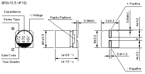
u Dimensions & Marking
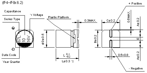
*1 Voltage mark [6V] represents 6.3V for Ф4~Ф10; *2 [L±0.3] is applicable to Φ6.3×7.7 and Φ8×6.2;
*3 [L±0.5] is applicable to Φ8×10.5~Ф10; *4 [L±1.0] is applicable to Φ12.5~Ф16.
Re: Date code and series type ― 1st digit for Year; 2nd digit for Quarter, 4 quarter codes in one year are 1, 4, 7, O;
3rd character for Series; LZ Series = L.
|
|
(mm) |
|
D×L |
Φ4×5.4 |
Φ5×5.4 |
Φ6.3×5.4 |
Φ6.3×7.7 |
Φ8×6.2 |
Φ8×10.5 |
Φ10×10.5 |
Φ10×13.5 |
Φ12.5×13.5 |
Φ12.5×16 |
Φ16×16.5 |
|
A |
1.8 |
2.1 |
2.4 |
2.4 |
3.3 |
2.9 |
3.2 |
3.2 |
4.7 |
4.7 |
5.5 |
|
B |
4.3 |
5.3 |
6.6 |
6.6 |
8.3 |
8.3 |
10.3 |
10.3 |
12.8 |
12.8 |
16.3 |
|
C |
4.3 |
5.3 |
6.6 |
6.6 |
8.3 |
8.3 |
10.3 |
10.3 |
12.8 |
12.8 |
16.3 |
|
E ± 0.2 |
1.0 |
1.3 |
2.2 |
2.2 |
2.2 |
3.1 |
4.4 |
4.4 |
4.4 |
4.4 |
6.7 |
|
L |
5.4 |
5.4 |
5.4 |
7.7 |
6.2 |
10.5 |
10.5 |
13.5 |
13.5 |
16.0 |
16.5 |
u Standard size & Maximum permissible ripple current & Impedance
|
WV Cap. (μF) |
6.3 |
10 |
16 |
|
0J |
1A |
1C |
|
10 |
100 |
|
|
|
|
|
|
4×5.4 |
3.0 |
60 |
|
15 |
150 |
|
|
|
|
|
|
5×5.4
(4×5.4) |
1.8
(3.0) |
95
(60) |
|
22 |
220 |
4×5.4 |
3.0 |
60 |
5×5.4
(4×5.4) |
1.8
(3.0) |
95
(60) |
5×5.4
(4×5.4) |
1.8
(3.0) |
95
(60) |
|
33 |
330 |
5×5.4
(4×5.4) |
1.8
(3.0) |
95
(60) |
5×5.4
(4×5.4) |
1.8
(3.0) |
95
(60) |
6.3×5.4
(5×5.4) |
1.0
(1.8) |
140
(95) |
|
47 |
470 |
5×5.4
(4×5.4) |
1.8
(3.0) |
95
(60) |
6.3×5.4
(5×5.4) |
1.0
(1.8) |
140
(95) |
6.3×5.4
(5×5.4) |
1.0
(1.8) |
140
(95) |
|
68 |
680 |
6.3×5.4
(5×5.4) |
1.0
(1.8) |
140
(95) |
6.3×5.4 |
1.0 |
140 |
6.3×7.7
(6.3×5.4)
(8×6.2) |
0.6
(1.0)
(0.6) |
230
(140)
(230) |
|
100 |
101 |
6.3×5.4
(5×5.4) |
1.0
(1.8) |
140
(95) |
6.3×7.7
(6.3×5.4)
(8×6.2) |
0.6
(1.0)
(0.6) |
230
(140)
(230) |
6.3×7.7
(6.3×5.4)
(8×6.2) |
0.6
(1.0)
(0.6) |
230
(140)
(230) |
|
150 |
151 |
6.3×7.7
(6.3×5.4) |
0.6
(1.0) |
230
(140) |
6.3×7.7
(6.3×5.4)
(8×6.2) |
0.6
(1.0)
(0.6) |
230
(140)
(230) |
6.3×7.7 |
0.6 |
230 |
|
220 |
221 |
6.3×7.7
(6.3×5.4)
(8×6.2) |
0.6
(1.0)
(0.6) |
230
(140)
(230) |
6.3×7.7
(8×6.2) |
0.6
(0.6) |
230
(230) |
8×10.5
(6.3×7.7)
(8×6.2) |
0.3
(0.6)
(0.6) |
450
(230)
(230) |
|
330 |
331 |
6.3×7.7
(8×6.2) |
0.6
(0.6) |
230
(230) |
10x10.5
(8×10.5) |
0.15
(0.30) |
670
(450) |
10×10.5
(8×10.5) |
0.15
(0.30) |
670
(450) |
|
470 |
471 |
8×10.5 |
0.30 |
450 |
10x10.5
(8×10.5) |
0.15
(0.30) |
670
(450) |
10×10.5
(8×10.5) |
0.15
(0.30) |
670
(450) |
|
680 |
681 |
8×10.5 |
0.30 |
450 |
10×10.5 |
0.15 |
670 |
10×10.5 |
0.15 |
670 |
|
1000 |
102 |
10×10.5
(8×10.5) |
0.15
(0.30) |
670
(450) |
10×10.5 |
0.15 |
670 |
10×13.5
(10×10.5) |
0.13
(0.15) |
750
(670) |
|
1500 |
152 |
10×13.5
(10×10.5) |
0.13
(0.15) |
750
(670) |
12.5×13.5
(10×13.5) |
0.11
(0.13) |
820
(750) |
12.5×13.5 |
0.11 |
820 |
|
2200 |
222 |
12.5×13.5
(10×13.5) |
0.11
(0.13) |
820
(750) |
12.5×16 |
0.09 |
950 |
16×16.5
(12.5×16) |
0.08
(0.09) |
1260
(950) |
|
3300 |
332 |
12.5×16
(12.5×13.5) |
0.09
(0.11) |
950
(820) |
16×16.5 |
0.08 |
1260 |
16x16.5 |
0.08 |
1260 |
|
4700 |
472 |
16×16.5 |
0.08 |
1260 |
16×16.5 |
0.08 |
1260 |
Case Size |
Impedance |
Ripple Current |
Maximum Impedance (Ω) at 20℃ 100kHz, Ripple Current (mA rms) at 105℃ 100kHz
u Standard size & Maximum permissible ripple current & Impedance
|
WV
Cap. (μF) |
25 |
35 |
50 |
|
1E |
1V |
1H |
|
1 |
010 |
|
|
|
4×5.4 |
3.0 |
60 |
4×5.4 |
5.0 |
30 |
|
1.5 |
1R5 |
|
|
|
4×5.4 |
3.0 |
60 |
4×5.4 |
5.0 |
30 |
|
2.2 |
2R2 |
|
|
|
4×5.4 |
3.0 |
60 |
4×5.4 |
5.0 |
30 |
|
3.3 |
3R3 |
|
|
|
4×5.4 |
3.0 |
60 |
4×5.4 |
5.0 |
30 |
|
4.7 |
4R7 |
4×5.4 |
3.0 |
60 |
4×5.4 |
3.0 |
60 |
5×5.4
(4×5.4) |
3.0
(5.0) |
50
(30) |
|
6.8 |
6R8 |
4×5.4 |
3.0 |
60 |
5×5.4 |
1.8 |
95 |
6.3×5.4 |
2.0 |
70 |
|
10 |
100 |
5×5.4
(4×5.4) |
1.8
(3.0) |
95
(60) |
5×5.4
(4×5.4) |
1.8
(3.0) |
95
(60) |
6.3×5.4 |
2.0 |
70 |
|
15 |
150 |
5×5.4 |
1.8 |
95 |
5×5.4 |
1.8 |
95 |
6.3×5.4 |
2.0 |
70 |
|
22 |
220 |
6.3×5.4
(5×5.4) |
1.0
(1.8) |
140
(95) |
6.3×5.4
(5×5.4) |
1.0
(1.8) |
140
(95) |
6.3×7.7
(6.3×5.4)
(8×6.2) |
1.0
(2.0)
(1.0) |
120
(70)
(120) |
|
33 |
330 |
6.3×5.4
(5×5.4) |
1.0
(1.8) |
140
(95) |
6.3×5.4
(8×6.2) |
1.0
(0.6) |
140
(230) |
6.3×7.7
(8×6.2) |
1.0 |
120 |
|
47 |
470 |
6.3×7.7
(6.3×5.4)
(8×6.2) |
0.6
(1.0)
(0.6) |
230
(140)
(230) |
6.3×7.7
(6.3×5.4)
(8×6.2) |
0.6
(1.0)
(0.6) |
230
(140)
(230) |
8×10.5
(6.3×7.7)
(8×6.2) |
0.6
(1.0)
(1.0) |
300
(120)
(120) |
|
68 |
680 |
6.3×7.7 |
0.6 |
230 |
6.3×7.7 |
0.6 |
230 |
8×10.5 |
0.6 |
300 |
|
100 |
101 |
6.3×7.7
(8×6.2) |
0.6
(0.6) |
230
(230) |
8×10.5 |
0.30 |
450 |
10×10.5
(8×10.5) |
0.30
(0.6) |
500
(300) |
|
150 |
151 |
8×10.5
(6.3×7.7) |
0.30
(0.6) |
450
(230) |
8×10.5 |
0.30 |
450 |
10×10.5 |
0.30 |
500 |
|
220 |
221 |
8×10.5 |
0.30 |
450 |
10×10.5
(8×10.5) |
0.15
(0.30) |
670
(450) |
10×13.5
(10×10.5) |
0.25
(0.30) |
580
(500) |
|
330 |
331 |
10×10.5
(8×10.5) |
0.15
(0.30) |
670
(450) |
10×10.5 |
0.15 |
670 |
16×16.5
(12.5×13.5)
(10×13.5) |
0.12
(0.20)
(0.25) |
1060
(650)
(580) |
|
470 |
471 |
10×10.5 |
0.15 |
670 |
12.5×13.5
(10×13.5)
(10×10.5) |
0.11
(0.13)
(0.15) |
820
(750)
(670) |
16×16.5
(12.5×16) |
0.12
(0.15) |
1060
(700) |
|
680 |
681 |
10×13.5 |
0.13 |
750 |
12.5×13.5
(10×13.5) |
0.11
(0.13) |
820
(750) |
16×16.5 |
0.12 |
1060 |
|
1000 |
102 |
16×16.5
(12.5×13.5) |
0.08
(0.11) |
1260
(820) |
16×16.5
(12.5×16) |
0.08
(0.09) |
1260
(950) |
|
|
|
|
1500 |
152 |
12.5×16 |
0.09 |
950 |
16×16.5 |
0.08 |
1260 |
|
|
Ripple Current |
|
2200 |
222 |
16×16.5 |
0.08 |
1260 |
|
|
|
Case Size |
Impedance |
|
|
|
|
|
|
|
|
|
|
|
|
Maximum Impedance (Ω) at 20℃ 100kHz, Ripple Current (mA rms) at 105℃ 100kHz
u Frequency Correction Factor of Rated Ripple Current
|
Frequency
Capacitance (μF) |
50Hz |
120Hz |
300Hz |
1kHz |
10kHz~ |
|
Φ4~Φ10 |
1~68 |
0.35 |
0.50 |
0.64 |
0.83 |
1.00 |
|
100~2200 |
0.40 |
0.55 |
0.70 |
0.85 |
1.00 |
|
Φ12.5~Φ16 |
~680 |
0.45 |
0.65 |
0.80 |
0.90 |
1.00 |
|
1000~4700 |
0.65 |
0.85 |
0.95 |
1.00 |
1.00 |