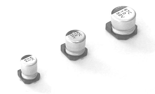
SC Low Leakage Current
n Low Leakage current (0.5μA to 3.3μA max.)
n Low cost for replacement of some tantalum applications
◆ Specifications
|
Items |
Performance Characteristics |
|
Operating Temperature Range |
-40~+85℃ |
|
Voltage Range |
6.3~50V |
|
Capacitance Range |
0.1~220μF |
|
Capacitance Tolerance |
±20% at 120 Hz, 20℃ |
|
Leakage Current |
After 2 minutes’ application of rated voltage, leakage current is not more than 0.002CV or 0.5(μA), whichever is greater. |
|
Surge Voltage & Tan δ(Max.) |
Measurement frequency: 120Hz, Temperature: 20℃
|
Rated voltage (V.DC) |
6.3 |
10 |
16 |
25 |
35 |
50 |
|
Surge voltage (V.DC) |
8.0 |
13 |
20 |
32 |
44 |
63 |
|
Tanδ (max) |
0.24 |
0.20 |
0.16 |
0.14 |
0.12 |
0.10 |
|
|
Stability at Low Temperature |
Measurement frequency: 120Hz
|
Rated voltage (V.DC) |
6.3 |
10 |
16 |
25 |
35 |
|
|
Impedance ratio
ZT/Z20 (max) |
Z-25℃/Z+20℃ |
4 |
3 |
2 |
2 |
2 |
2 |
|
Z-40℃/Z+20℃ |
8 |
6 |
4 |
4 |
3 |
3 |
|
|
Load Life |
After 2000 hours’ application of rated voltage at 85℃, capacitors meet the characteristics requirements listed at right.
|
|
Capacitance Change |
Within ±25% of the initial value |
|
Tanδ |
200% or less of the initial specified value |
|
Leakage Current |
Initial specified value or less |
|
|
|
After reflow soldering and restored at room temperature, they meet the characteristics requirements listed at right.
|
|
Capacitance Change |
Within ±10% of the initial value |
|
Tanδ |
Initial specified value or less |
|
Leakage Current |
Initial specified value or less |
|
|
Applicable Standards |
JIS C-5141 and JIS C-5102 |
◆ Dimensions & Marking
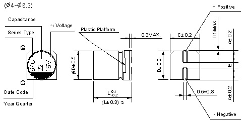
*1 Voltage mark for 6.3V is [6V] *2 Applicable to 6.3×7.7
Re: Date code and series type - 1st digit for Year; 2nd digit for Quarter, 4 quarter codes in one year are 1, 4,7,O;
3rd character for Series; SC Series = C.
(mm)
D×L |
Φ4×5.4 |
Φ5×5.4 |
Φ6.3×5.4 |
Φ6.3×7.7 |
|
A |
1.8 |
2.1 |
2.4 |
2.4 |
|
B |
4.3 |
5.3 |
6.6 |
6.6 |
|
C |
4.3 |
5.3 |
6.6 |
6.6 |
|
E ± 0.2 |
1.0 |
1.3 |
2.2 |
2.2 |
|
L |
5.4 |
5.4 |
5.4 |
7.7 |
◆ Standard size & Maximum E.S.R & Maximum permissible ripple current
|
WV
Cap. (μF) |
6.3 |
10 |
16 |
|
0J |
1A |
1C |
|
10 |
100 |
|
|
|
|
|
|
4×5.4 |
34.5 |
25 |
|
22 |
220 |
4×5.4 |
23.5 |
31 |
5×5.4 |
19.6 |
35 |
5×5.4 |
15.7 |
39 |
|
33 |
330 |
5×5.4 |
15.7 |
39 |
5×5.4 |
13.1 |
43 |
6.3×5.4 |
10.5 |
57 |
|
47 |
470 |
5×5.4 |
11.0 |
47 |
6.3×5.4 |
9.2 |
59 |
6.3×5.4 |
7.3 |
68 |
|
100 |
101 |
6.3×5.4 |
5.2 |
75 |
6.3×5.4 |
4.3 |
76 |
6.3×7.7 |
3.5 |
96 |
|
220 |
221 |
6.3×7.7 |
2.4 |
85 |
|
|
|
Case Size |
ESR (max) |
Ripple Current |
Max. E.S.R. (Ω) at 20℃ 120Hz, Ripple Current (mA rms) at 85℃ 120Hz
|
WV
Cap. (μF) |
25 |
35 |
50 |
|
1E |
1V |
1H |
|
0.1 |
0R1 |
|
|
|
|
|
|
4×5.4 |
2156 |
1.0 |
|
0.22 |
R22 |
|
|
|
|
|
|
4×5.4 |
980 |
2.3 |
|
0.33 |
R33 |
|
|
|
|
|
|
4×5.4 |
653 |
3.5 |
|
0.47 |
R47 |
|
|
|
|
|
|
4×5.4 |
459 |
5 |
|
1 |
010 |
|
|
|
|
|
|
4×5.4 |
216 |
10 |
|
2.2 |
2R2 |
|
|
|
|
|
|
4×5.4 |
98 |
15 |
|
3.3 |
3R3 |
|
|
|
|
|
|
4×5.4 |
65 |
18 |
|
4.7 |
4R7 |
4×5.4 |
64.2 |
19 |
4×5.4 |
55.1 |
20 |
5×5.4 |
46 |
23 |
|
10 |
100 |
5×5.4 |
30.2 |
28 |
5×5.4 |
25.9 |
30 |
6.3×5.4 |
22 |
34 |
|
22 |
220 |
6.3×5.4 |
13.7 |
52 |
6.3×5.4 |
11.8 |
54 |
6.3×7.7 |
9.8 |
85 |
|
33 |
330 |
6.3×5.4 |
9.1 |
63 |
6.3×7.7 |
7.8 |
105 |
Case Size |
ESR (max) |
Ripple Current |
|
47 |
470 |
6.3×7.7 |
6.4 |
100 |
6.3×7.7 |
5.5 |
110 |
Max. E.S.R. (Ω) at 20℃ 120Hz, Ripple Current (mA rms) at 85℃ 120Hz
◆ Frequency Coefficient Factor of Rated Ripple Current
|
Frequency |
~50Hz |
120Hz |
300Hz |
1kHz |
10kHz~ |
|
Coefficient |
0.7 |
1 |
1.17 |
1.36 |
1.50 |